We offer a wide range of internal power supplies in open frame, enclosed, and DIN Rail packaging with various ventilation and mounting options to suit any of your specifications. We also have a wide range of external wall mount and desktop units
AC/DC Power Supplies
Robust and versatile power supplies for every application
Explore our extensive range of AC/DC power supplies, all carefully engineered to provide stable and efficient voltage conversion for a vast array of applications. From consumer electronics to industrial automation and medical devices, our AC/DC power solutions are designed to meet the most demanding requirements for performance, safety, and reliability.
Explore our extensive range of AC/DC power supplies, all carefully engineered to provide stable and efficient voltage conversion for a vast array of applications. From consumer electronics to industrial automation and medical devices, our AC/DC power solutions are designed to meet the most demanding requirements for performance, safety, and reliability.

Browse our extensive range of AC/DC power supplies
From compact 1-watt units to robust 3600-watt powerhouses, our diverse range of AC/DC power supplies ensures you'll find the perfect fit for your project.
Tailored power for any device
Our AC/DC power supplies offer a wide range of voltage and current options, from low-power outputs for portable devices to high-power outputs for demanding industrial machinery.
This flexibility allows you to precisely match the power supply to the needs of your specific application, ensuring optimal performance and efficiency.
Whether you’re powering a complex automation system, an electric vehicle, or a simple appliance, our wide selection of output configurations has you covered.
Features
- Output ranges from 1W to 3600W
- Universal input ranges for global compatibility
- Single and multi-output options
- Short circuit and over-power protection
- Low ripple and noise
- Widely recognized safety and testing approvals
- Extensive range of mount options
- Wide operating temperature ranges
Applications


Find a high voltage AC DC Power Supply solution
Our diverse range includes hundreds of product families, easily searchable by voltage, power, format and application.
Search AC/DC Power Supplies
Built-in protection for peace of mind
Safety and reliability are paramount in any electrical application.
Our AC/DC power supplies come equipped with a range of protective features to safeguard your devices and avoid unforeseen outages.
Overvoltage and overcurrent protection prevent electrical damage, short circuit protection safeguards the power supply itself, and input protection shields against voltage fluctuations.
With our focus on safety, you can trust our power supplies to deliver reliable performance in even the most demanding environments.
Flexible configurations for seamless integration
Every project has unique space and mounting constraints.
Our AC/DC power supplies come in a variety of configurations to address these challenges. Choose from DIN rail mount options for industrial control panels, PCB mount for direct board integration, chassis mount for simple and secure enclosure installation, or convenient external wall mount and desktop designs.
With this versatility, you can easily incorporate our power supplies into any setting, from a compact diagnostic tool, to an expansive lighting display or automation on a factory floor.

| Series | Input Range |
Input Voltage |
Output Voltage |
No. Outputs |
Output Power (W) |
|
|---|---|---|---|---|---|---|
PSAYC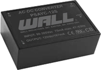 Series Description: The PSAYC series of AC/DC switching power supplies provides 2 watts of output power in a 1.33" x 0.87* x 0.67* encapsulated PCB mountable package. | Input Voltage: 90~305 | Input Voltage: 115/230 | Output Voltage: 3.3, 5, 9, 12, 15, 24 | No. Outputs: S | Output Power (W): 2 | Get a QuoteDownload Datasheet |
AC DC Power Supplies - The PSAYC series of AC DC power supplies provides 2 Watts of output power in an encapsulated PCB mountable package. This series consists of single output models with a 90-305VAC (120-430VDC) input voltage range. | ||||||
PSAZC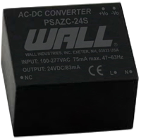 Series Description: The PSAYC series of AC/DC switching power supplies provides 2 watts of output power in a 1.33" x 0.87* x 0.67* encapsulated PCB mountable package. | Input Voltage: 90~305 | Input Voltage: 115/230 | Output Voltage: 3.3, 5, 9, 12, 15, 24 | No. Outputs: S | Output Power (W): 2 | Get a QuoteDownload Datasheet |
AC DC Power Supplies - The PSAZC series of AC DC power supplies provides 2 Watts of output power in an encapsulated PCB mountable package. This series consists of single output models with a 90-305VAC (120-430VDC) input voltage range. | ||||||
WMSAW06D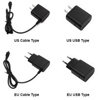 Series Description: The PSAYC series of AC/DC switching power supplies provides 2 watts of output power in a 1.33" x 0.87* x 0.67* encapsulated PCB mountable package. | Input Voltage: 100~240 | Input Voltage: 115/230 | Output Voltage: 5, 6, 9, 12, 24 | No. Outputs: S | Output Power (W): 2.5, 4.5, 5, 6 | Get a QuoteDownload Datasheet |
The WMSAW06D series of AC DC wall mount power supplies offers up to 6 watts of output power in a light weight and compact package. This series consists of single output models with a universal input range of 90~264VAC. | ||||||
WMSBW06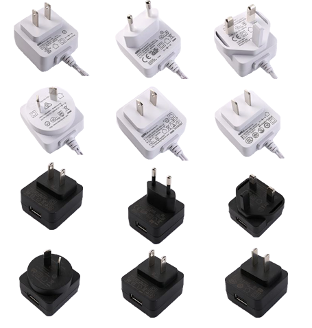 Series Description: The PSAYC series of AC/DC switching power supplies provides 2 watts of output power in a 1.33" x 0.87* x 0.67* encapsulated PCB mountable package. | Input Voltage: 90~264 | Input Voltage: 115/230 | Output Voltage: 5, 9, 12, 24 | No. Outputs: S | Output Power (W): 2.5, 5, 6, 6.03 | Get a QuoteDownload Datasheet |
The WMSBW0606 series of AC/DC wall mount power supplies offers up to 6.03 watts of output power in a small 1.72” x 1.61” x 0.90” package. | ||||||
PSAIC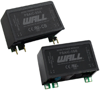 Series Description: The PSAYC series of AC/DC switching power supplies provides 2 watts of output power in a 1.33" x 0.87* x 0.67* encapsulated PCB mountable package. | Input Voltage: 90~264 | Input Voltage: 115/230 | Output Voltage: 3.3, 5, 9, 12, 15, 24 | No. Outputs: S | Output Power (W): 2.97, 3 | Get a QuoteDownload Datasheet |
AC DC Power Supplies - The PSAIC series of AC DC switching power supplies offers 3W of output power in an encapsulated PCB mountable package. This series consists of single output models with a 90-264VAC (120-370VDC) input voltage range. | ||||||
PSFAA-03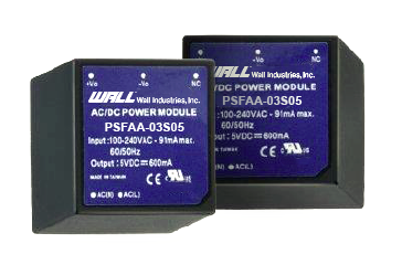 Series Description: The PSAYC series of AC/DC switching power supplies provides 2 watts of output power in a 1.33" x 0.87* x 0.67* encapsulated PCB mountable package. | Input Voltage: 85~264 | Input Voltage: 115/230 | Output Voltage: 3.3, 5, 9, 12, 15, 24 | No. Outputs: S | Output Power (W): 3 | Get a QuoteDownload Datasheet |
The PSFAA-03 series of AC/DC power modules offers up to 3 watts of output power in a fully encapsulated 1” x 1” x 0.64” plastic case. | ||||||
PSAOC Series Description: The PSAYC series of AC/DC switching power supplies provides 2 watts of output power in a 1.33" x 0.87* x 0.67* encapsulated PCB mountable package. | Input Voltage: 90~264 | Input Voltage: 115/230 | Output Voltage: 3.3, 5, 8, 9, 12, 14, 15, 24 | No. Outputs: S, D | Output Power (W): 3.5, 3.6, 3.96, 4 | Get a QuoteDownload Datasheet |
AC DC Power Supplies - The PSAOC series of AC DC power supplies provides 4 Watts of output power in an encapsulated PCB mountable package. This series consists of single output models with a 90-264VAC (120-370VDC) input voltage range. | ||||||
PSAOCH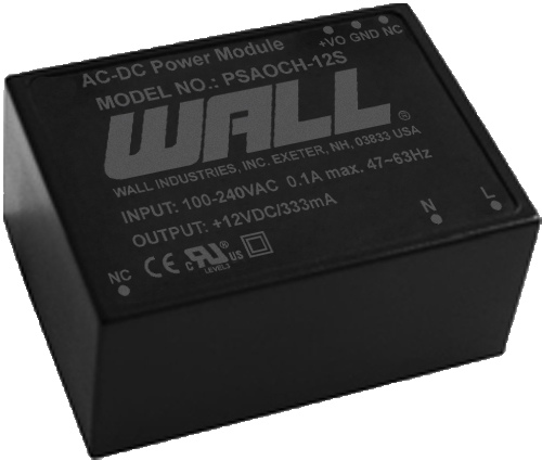 Series Description: The PSAYC series of AC/DC switching power supplies provides 2 watts of output power in a 1.33" x 0.87* x 0.67* encapsulated PCB mountable package. | Input Voltage: 90~305 | Input Voltage: 115/230 | Output Voltage: 3.3, 5, 8, 9, 12, 14, 15, 24 | No. Outputs: S, D | Output Power (W): 3.5, 3.6, 3.96, 4 | Get a QuoteDownload Datasheet |
AC DC Power Supplies - The PSAOCH series of AC DC switching power supplies offers 4W of output power in an encapsulated PCB mountable package. This series has single and dual output models available with a 90-305VAC (120-430VDC) input voltage range. | ||||||
WMGPSU06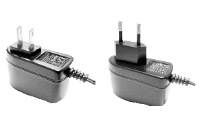 Series Description: The PSAYC series of AC/DC switching power supplies provides 2 watts of output power in a 1.33" x 0.87* x 0.67* encapsulated PCB mountable package. | Input Voltage: 100~240 | Input Voltage: 115/230 | Output Voltage: 3~5, 5~6, 6~8, 8~11, 11~13, 13~16, 16~21, 21~27, 27~33, 33~48 | No. Outputs: S | Output Power (W): 4, 6 | Get a QuoteDownload Datasheet |
The WMGPSU06 series of AC/DC wall mount power supplies offers up to 6 watts of output power in a compact package. | ||||||
WMGPSU06x-CC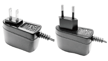 Series Description: The PSAYC series of AC/DC switching power supplies provides 2 watts of output power in a 1.33" x 0.87* x 0.67* encapsulated PCB mountable package. | Input Voltage: 100~240 | Input Voltage: 115/230 | Output Voltage: 3~5, 5~6, 6~8, 8~11, 11~13, 13~16, 16~21, 21~27, 27~33, 33~48 | No. Outputs: S | Output Power (W): 4, 5, 6 | Get a QuoteDownload Datasheet |
The WMGPSU06X-CC series of AC/DC wall mount power supplies offers up to 6 watts of output power in a 2.60” x 1.26” x 1.67” compact package. | ||||||
What is an AC DC power supply?
An AC DC power supply is an electric device that transforms alternating current into direct current which can be used to power other electrical devices. Power provided to homes typically comes in the form of AC, and as most consumer electronic devices require DC, AC DC power suppliers are in much demand.
Can you use an AC power supply for DC?
In some cases, it is possible to use and AC power supply for DC.
How do AC to DC power supplies work?
AC to DC power supplies consist of a number of components that combine to perform their function. The transformer changes the incoming voltage to the appropriate outgoing voltage level. The rectifier converts the power source from AC to DC.
A filter then smooths out the waves caused by the power being converted which outputs unregulated power. Finally, a voltage regulator reduces ripple left by the filter, and cuts out surges that could damage connected devices.
What industries use AC DC power supplies?
AC/DC power supplies can be used across various industries including the Military, Lighting, Industrial, Manufacturing, Robotics, Automation and Electric Vehicles.
What medical equipment can be powered by AC DC power supplies?
Many of our AC DC power supplies meet requirements for medical safety standards including IEC 60601-1. This allows the units to be used safely in medical devices around patients, including ventilators, patient monitoring devices, diagnostic equipment, as well as beds and other motor-driven equipment.
What is the main difference between AC DC and DC DC power supplies?
The main difference between the AC DC and DC DC power supplies is the direction their electrons flow. AC DC power supplies has an alternating current, where the electrons continuously change direction. On the other hand, electrons in DC DC power supplies flow steadily in the same direction.
What Industrial equipment can be powered by AC DC power supplies?
AC DC power supplies are commonly used in factory automation, robotics, signage and manufacturing equipment, due to their wide temperature range, high reliability and safety features.
Get a Quote
Request information for from Wall Industries.
"*" indicates required fields
Custom Solutions
Wall Industries, Inc. offers fully custom power design capabilities. Our team of electrical and mechanical power design engineers will utilize proven design topologies and concepts to create a solution to your power requirements. If you don’t have a specification, Wall’s engineering team will assist you in determining what your requirements are and how best to provide a solution.
Custom Power Supplies