


Introduction
Everyone is looking to find the perfect power supply for their project. This means it meets all required specs, fits in the budget, and works how it is supposed to. Seems simple enough. But, time and time again, we see projects failing and power supplies that do not seem to work as they should. This is usually the result of a fault made at some point in the research and design process; mainly when choosing the power supply. This white paper will take you through the top mistakes encountered when choosing a power supply, the questions to ask, and the answers that will help avoid error in the future.
Contents:
1. Input Voltage Conditions
2. Load Conditions
3. Environmental Conditions
4. Installation
5. Safety
| Download This Article |
Input Voltage Conditions
Is the Input Voltage Range Correct? Is a Wider Range Needed? What is the Hold Up Time?
One of the most crucial points to consider in your power supply is your input voltage, so it is important you are choosing the correct range. The range you need will be determined by the application being used. If you choose a supply that has an input range that is not wide enough, the supply will not be able to work over the complete line voltage. Every supply has a minimum voltage that the supply is able to work at, and if the input voltage range cannot reach this minimum, the supply will shut down and fail to work.
So when should you be looking for a wide input voltage range?
High Voltage Drop: Wide input voltage ranges are typically needed in applications that have a high voltage drop in the source lines, which cause high fluctuations in the voltage at the input of the supply.
High Hold Up Time: If your supply requires a high hold up time, it means that there is a risk of it losing input power for a short amount of time during use. In order to keep the supply working properly, a wide input voltage range should be chosen, to allow the supply to continue to operate as the input voltage decreases.
When Universal Input is Needed: Different countries have different input voltage regulations. This means that if you know you will be using a certain supply in the US, Japan, and Europe, for example, you should be choosing a supply with the wide, universal input range of 90~264VAC so it will not fail during use.
Remember: Using a wider voltage range can reduce the need for two separate parts.
Is PFC Needed Or Not? What is the Level of Acceptable PFC and THD?
When choosing an AC/DC power supply, it is very important to take power factor correction (PFC) into account. PFC is a component that can be added to a supply that will help combat bad power factor as well as THD imposed back onto the line. There are many factors to consider before adding PFC, overall wattage of the supply, industry, location to be used and, most importantly, what an acceptable power factor for your supply will be. Below, we’ve listed out some helpful ways to know if you’ll need to add PFC to your supply:
Poor Power Factor: Power factor (PF) is a delay between the current and
the voltage that, ideally, should not occur. Ideal power factor is 1, yet this level is not required for all supplies. For example, a power factor of 0.9 may be sufficient for your supply, and PFC would need to be added if PF dropped below this level. The best way to determine the acceptable PF level in your supply is to reference the data sheet.
Not Enough Power Available At Input: If a certain amount of power is needed for a supply, that is not being supplied initially, adding PFC can help achieve the needed power level. For example: If 10 amps is being supplied by the power company, but your supply needs a 20 amp peak due to poor PF, that will obviously not work. Adding PFC will average out the input current, lowering the peak required.
Wider Input Voltage Range is Needed: PFC is able to supply universal AC input voltage (90~264VAC) and yield a fixed DC voltage for the supply to operate from. Adding PFC can help achieve a universal input range for your supply.
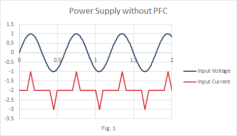
Problems with Total Harmonic Distortion (THD): THD occurs in a supply when the current waveform is not sinusoidal, like in the graph in Fig. 1. THD causes problems with interference, EMI, and degrading of conductors and insulating materials. Adding PFC can help combat THD.
There Is A PFC or THD Regulation in the Country of Your End Supply: One thing to keep in mind is that some countries have regulations for both PFC and THD. Make sure you check regulations before adding PFC to your supply.
When you figure out that PFC needs to be included in your supply, there are some things that should be kept in mind. When PFC is added, more loss will occur due to the double processing or power that is occurring. Essentially you are running two separate power supplies, each experiencing their own loss. This extra power also results in more heat being released, and therefore the possible need for cooling increases. This will mean more weight and size will be added to the supply so it is important that the environment around the supply can compensate for these changes. Adding PFC will also cause the cost of the supply to go up.
Is the Inrush Current Correct?
Keep your eye on the inrush current when you are choosing a supply for your power project. If you require a device to start up quickly, you need all the charging elements, like capacitors or inductors, to power up quickly and get your supply working. This is when inrush current comes in. The inrush current delivers the energy needed to charge these elements, and it is important that it is not too high. The supply you are choosing needs to have an inrush current that will match up with the electrical source circuit or electrical line circuit. The maximum inrush current is set by the power provider (i.e., circuit breaker), and should not be exceeded.
If you select an inrush current that is higher than the set maximum, it can cause a lot of problems with your supply. Not only could it cause the supply to disconnect the circuit breaker or cause a blown fuse, but it can also shorten the life of your supply. High inrush current places stress on the electronic elements, causing them to wear down and have a shorter life.
If you have a fast start up time and want to lower the inrush current, it is necessary to reduce the energy storage capacity (extra capacitance) at the input. In an AC/DC supply, a lower storage capacity can be reached with multiphase input voltage.
If your supply does not require a fast startup time, then it is easy to decrease the inrush current. It is important to keep in mind that if the inrush current is too low, any interruption of the input voltage will cause the unit to lose power very quickly. Make sure you are checking your maximum inrush current values.
Load Conditions
Is the Chosen Output Capacitor Correct?
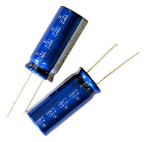
If your supply will need an external output capacitor, it is important that
you are choosing one that will work properly for your supply. Capacitors are components that decrease the voltage ripple of a supply and help store output power for a longer period of time. They help stabilize the output and improve the ripple of the supply.
There are a few different variations of capacitors namely electrolytic, aluminum, ceramic, and polyester. Electrolytic and aluminum capacitors are typically used in older, lower switching frequency supplies while ceramic and polyester capacitors are used in newer, higher switching frequency supplies.
If the chosen capacitor is wrong, it can have different effects on your supply and how it works. The best way to make sure the capacitor is correct is to reference the data sheet.
If the capacitor is too big: The supply can be shut down at start-up due to over current to charge the capacitor.
If capacitance is too low: Excessive ripple can occur.
Remember: If the supply you are considering has internal capacitance, then an output capacitor may not be necessary. Sometimes a specific amount of external capacitance can be used; make sure to check the supply spec.
What Type of Load is it? Capacitive vs. Inductive vs. Resonant
The type of load your end project presents is vital information to know because it will determine what kind of power supply you will need. If the type of load is unknown, the supply may not be able to work as intended, causing problems. Below are the types of loads to look for and the supplies that coincide with them:
Capacitive Load:
- What is it: Load is a voltage source like another power supply; Capacitor is unable to make large voltage change in short time periods
- Benefits: Not a high rate of voltage change
- Risks: Output sees a short circuit at T=0 causing an initial short circuit condition
- Works best with: Voltage controlled supply, Switching power supply, Battery, Supplies that need open circuit protection
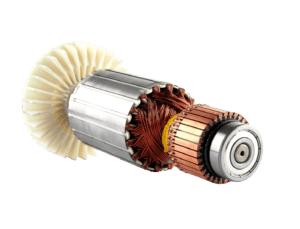
Inductive Load:
-

Electric Motor Rotor
What is it: Load is inductive: battery charger, electrical motor, solenoid
- Benefits: Slow rate of current change; works well in short circuit
- Risks: Huge overvoltage in open circuit conditions. If the output current is quickly disconnected an inductive kick could occur.
- Works best with: Current controlled supply, Short circuit protection
Resonant Load:
- What is it: When a resonant tank is present that needs to be charged by input power at startup. Resonant loads have resonant frequency that the supply will have to work at.
- Benefits: Lower current and voltage supply can be used due to power generated in resonant tank.
- Risks: Open circuit if required frequency is strayed from; hard to work with open circuit and short circuit; more complicated control circuits
- Works best with: Supply with frequency modulation control.
If the supply has a very specific load, some design features may need to change.
Do I Need to Protect Against Back EMF?
If the switch mode supply you are choosing powers an inductive load, the power supply needs to be protected against back EMF (electromotive force). Back EMF occurs when using an electromechanical machine (like an electrical motor) turns electrical energy to mechanical energy. During brake time, mechanical energy is turned back to electrical energy and tries to return to the supply. This is when EMF occurs.
This returning energy should be either stored by a capacitor or inductor in the supply or dissipated from the supply by a resistor. If the energy is going to be stored, it will result in less loss and higher efficiency, but the circuit will be a lot more complicated. In contrast, dissipating the energy calls for a less complicated design and more reliability, but a higher loss and lower efficiency. These are options to weigh when deciding how to deal with back EMF.
 The need to protect against back EMF will be obvious if the supply you are looking has a load with EMF involved (like a motor). While using the supply, if an overvoltage rating past the safe voltage rating occurs, it is time to protect against back EMF. If back EMF occurs, it can create overvoltage and damage the supply. Keep this in mind and make sure you are using a method that will work best for your application.
What is the Rate of Load Change?
Load change is a specification that should be chosen based on application. Supplies that require a fast response need to consider a fast load change, from 10%-90% for example. Some of these applications are relay testing, data power centers, and nuclear applications. Applications like these need to have a very fast rate of load change in order to avoid lag time. If the supply cannot react fast enough to a load change, failure in power delivery can result.
A slower rate of load change is needed in applications that typically perform more slowly. Pretty much any process that won’t be negatively affected by a lag in load demand can have a slower rate of load change. This can be for applications involving heat, electrolysis and electro coating just to name a few. In these slower applications, it is okay for the load not to change too quickly, so using a supply that is too fast can result in unnecessary cost.
Remember: Required rate of load change cannot be changed, supply response can only be made faster or slower.
Environmental Conditions
How Will Environmental Conditions Around Supply Affect Its Function?
High Altitude
Power supplies often see failure at high altitudes. When altitude is forgotten in the power supply decision process, the supply can often be placed in
an elevation that will cause it to fail due to poor insulation and thermal management. At high altitudes, the air is less dense, can transfer less heat from the supply, and is no longer a good electrical insulator for the supply. How can you plan for a high altitude situation when choosing your power supply?
Bigger Heatsink: By adding a bigger heatsink to your supply, it can then compensate for the air’s inability to transfer heat. Heatsinks are better suited for smaller supplies as they will affect the size, weight and form factor.
Fluid Heat Transfer: Using fluid heat transfer allows you to transfer heat at a higher rate through the use of a smaller heatsink and flowing liquid. This will result in a smaller power supply. The drawback with fluid heat transfer is that access to circulating liquid is necessary for it to be a possibility.
Electrical Isolation: If internal conductors are placed too close together in the power supply, spark or short circuit can occur. Isolation of the supply can protect against this, but enough space needs to be allotted for it. If you know your supply will be in a high altitude environment, it is best to “over-design” required distance for isolation and thermal transfer rate. For example, if you only need 1mm by distance, design with 2mm distance instead. This extra space will allow a safe distance between the conductors, and a safe distance for isolation.
Remember: It is important to be aware of thermal management and isolation issues that high altitude environments can cause. Make sure you know the environment your supply will be in and make plans in the design stages to prevent against failure.
Shock and Vibration
Placing a supply in an environment with shock and vibration present can
be very risky to the supply if it is overlooked. Shock and vibration are most commonly a result of an environment that moves parts. This can be anything from a motor to a cooling fan, though the range of shock and vibration they will cause will vary. Even the smallest amount of shock and vibration can cause stress on the PCB, component leads, and solder joints, just to name a few. Shock and vibration can be measured with an acceleration sensor. Depending on the level and type of shock and vibration, the following solutions can help protect your supply:
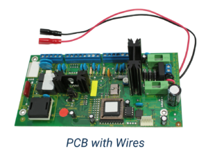 Choosing a More Suitable Wire: Shock and vibration can really take a toll on the wires of your supply. If your supply is using a solid wire and connector, this can cause damage. Flexible wires are more suitable in this environment because they do not break as easily.
Choosing a More Suitable Connector for PCB: It is not a good idea to connect to the supply to the PCB load without careful consideration in a shock and vibration environment. If it is absolutely necessary though, PCBs should not be directly connected. They should be attached via flexible wires in order to prevent breakage.
Tying Down Cables if Present: If the cables in and around your supply are not tied down, they can move and will most likely break.
Coating PCB for Damping: Coating acts as a damper and absorbs vibration. Adding coating increases cost and makes repairing the supply more difficult.
Staking Parts on Board with Epoxy: Attaching the parts to the PCB with epoxy offers better stabilization.
Placing an Isolator between PCB and Enclosure: An isolator consists
of components that can help absorb the shock and vibration from
the environment, preventing damage to the supply. Adding an isolator unfortunately adds cost to the supply and makes the assembly more complicated. It can also be a detriment to conductive cooling.
High Temperature
High temperature can have a variety of effects on a power supply. It is vital that you prepare your power supply if it will be placed in a high temperature environment. Most evidently, a high temperature environment will cause the supply to overheat. High temperatures can cause the reliability of the supply to decrease and ultimately shorten the life of the supply. It also decreases conductivity which results in a higher conductive loss as copper resistance rises with temperature. High temperature can cause high wear in moving parts as well as decrease of dielectric and insulator failure. There are a few ways that high temperature environments can be dealt with when choosing a power supply:
Attach a Heatsink: Heatsinking can be added to help with thermal management. Remember that adding a heatsink will increase the weight and size of the supply. Make sure these factors are taken in to consideration if heatsink will be added.
Use a Suitable Mechanical Structure: If you don’t decide to add a heatsink, make sure you choose a supply that has expansion flexibility. In the case that a heatsink is needed or the supply needs to be enlarged, make sure you choose a design that can expand easily.
Use the Supply at Lower Voltage and Lower Current Level than Rated for: This will generate less heat, increase reliability, and prevent the supply from overheating.
Use Larger Traces: To prevent resistance and ultimately conductive loss, the trace that the current flows on needs to be bigger. If the part is staying the same size, but the trace is bigger, current can flow with less resistance and conductive loss is prevented.
Remember that there can be some benefits to high temperature situations.
If IGBT or bipolar diode is being used, they can get better conduction loss. Some cases may also show better magnetic core loss resulting from a high temperature environment.
Remember: When a supply will be going into a high temperature environment, remember to look at everything the temperature will affect: temperature rating, thermal management, change in material properties (viscosity, expansion, etc.). Think about how each will be affected and plan accordingly.
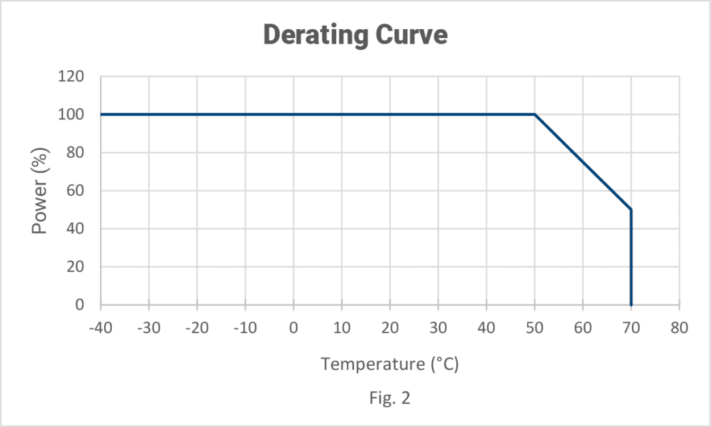
What is the Voltage Derating Point and the Voltage Shutdown Point?
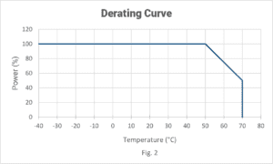
Derating can be vital to the longevity of your power supply. To put it simply, derating is the process of decreasing the output power below maximum capacity so that your supply can continue operating at the necessary voltage, current, temperature etc. It is very important to take derating levels into account when choosing your supply as you do not want to over derate the supply.
When choosing a power supply, keep your eye on the derating graphs. They will show operating levels for derating and what the derating point will be. For example, the temperature derating point is the temperature at which your supply will start decreasing output power to maintain proper levels. It will allow you to know the capacity that your supply will be able to operate at over a certain temperature range. You need to make sure that once it hits this point, it will still be able to operate properly for your application.
Similarly, you need to be aware of the shutdown point of your supply. The shutdown point is the level at which, you guessed it, your supply will shut down. The shutdown point can be important to know for many reasons. One is output current. A load that is too high can cause a supply to shut down and then to restart. Low input voltage is another reason. Some supplies have under voltage lock out points where the supply shuts down when a certain low input voltage is detected. High temperature can cause a supply to shutdown until it is cool enough to restart.
Remember: Voltage derating point of a supply can be changed, though this will increase
the price of the supply.
Installation
Is Enough Space Allotted for My Supply?
The size of your supply is arguably one of the most important aspects to consider in the design and decision process. Your supply definitely needs to fit in the space available for it, but it is often forgotten that the smaller the supply is, the more expensive it will end up being.
Using a smaller supply may be necessary due to the size and weight restrictions, but a large supply may be needed to fit budget restrictions. Naturally, there are pros and cons to both small supplies and large supplies.
| Small Supplies | |
| Pros | Cons |
| Take Up Less Space Less Mass Lower Conduction Loss |
More Expensive Can Require External Circuiting for EMI and Storage |
| Large Supplies | |
| Pros | Cons |
| Less Expensive Easier Thermal Management Uses Lower Frequency |
Use Up Space Adds Weight |
Remember: A bigger supply may seem too good to be true if you are looking to save on cost. If you opt for a larger, less expensive supply, make sure that enough space is allotted for it and that it meets all necessary specifications. This will prevent failure of the supply.
Do I Need to Use an Active or Passive Cooling Method?
The cooling of your power supply can be a vital aspect to its longevity and success. There are two types of cooling that can be used: passive or active. The type you need will be determined by the amount of heat you need to transfer.
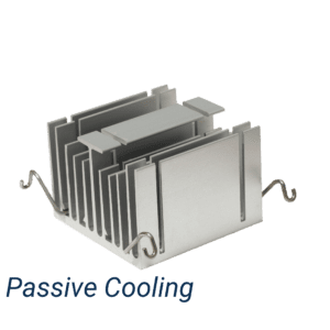 If the amount of heat you need to transfer is low enough, passive cooling can be utilized. Passive cooling amounts to conduction (via heatsink) or natural convection. Passive Passive Cooling cooling does not require many complicated parts, but is also not able to transfer a lot of heat. Passive cooling is best for supplies that are more efficient and are big enough to transfer heat by the air. Supplies that are in high-vibration environments should also use passive cooling.
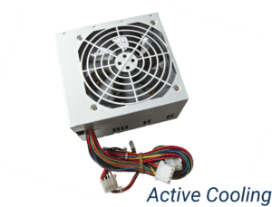 If the required level of heat transfer is large, then active cooling needs to be used. Very simply, active cooling involves an element that is actively cooling the supply, such as a fan or a heatsink with water flowing inside. Though active cooling uses more parts, it allows the supply to transfer a lot more heat, much faster than passive cooling can. Using active cooling will ultimately result in lower reliability (the more parts you have, the more chance for failure!) but if passive cooling won’t cut it, active cooling will need to be used. Make sure you pay attention to the amount of heat transfer you need; this will determine your cooling type.
Is an External Heatsink Needed?
Heatsink allows heat produced by the supply to be transferred to the air through convection provided that the supply is designed to be conduction cooled. This can allow the device to have a longer life as high temperature can damage the device.
More often than not, the heatsink in your device will be internal. If an internal heatsink is not available, then adding an external heatsink will need to be considered. External heatsink will only be possible for certain designs, and it will make the supply larger and heavier (which the design will need to compensate for).
You will know if you need an external heatsink through the spec sheet. Keep in mind that if the wrong heatsink is chosen, the supply can be damaged or operate at lower reliability.
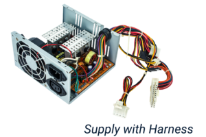
How Much Distance is Between the Power Supply, the Load, and Input Power? Is a Harness Needed?
The distance between the supply and the load is very important to keep in mind as the supply and the load need to be the appropriate distance from each other. If the supply and the load are too close together, shielding and EMI protection may be necessary. If there is too much distance between them, a harness will be needed to connect the supply to the load.
A harness will be needed in most situations and will ultimately affect the electrical characteristics of the supply. When considering the harness, it is important to remember the following:
- How it will affect the power supply by adding extra capacitance and inductance.
- The type, size, endings and connections of the harness wires, & how they will affect your supply.
- The harness needs to be placed in a safe area to avoid a tripping hazard or effects of EMI from other devices.
- Know the allowable inductance of the harness. Inductance can cause extra voltage and slow the current change.
Is There Clearance Available Between the Power Supply and Any Adjacent Equipment?
When thinking about the installation of your supply, it is important to consider the distance needed between the supply and the equipment surrounding it. If there is not clearance, the power supply is unable to transfer heat to surrounding area. If the supply is too close to equipment, electrical noise, extra heat, and dust can cause the supply to fail. Some of these factors can be fixed by external parts. Electrical noise is combatted by shielding, extra heat can be fixed by a fan, and dust can be prevented through an electro filter. The easiest way to prevent these though, is by referencing the installation manual, and leaving enough space between your supply and any adjacent equipment.
Safety
What are the Safety Standards Needed for My Supply?
It is vital that the power supply you choose is up to current safety standards. Depending on the application, environment, and country of your end design, your supply needs to be up to date and safe to use. Below are some safety specifications to keep in mind.
Industrial Application
| Category | Sub-Category | Standard | Region |
| Electro-Magnetic | Generic Industrial | IEC 61000-6-2 | Global |
| IEC 61000-6-4 | |||
| EMC Standard for Measurement, Control, and Lab Use | EN 61326-1 | ||
| Generic Industrial | BS EN 61000-6-4 | UK | |
| BS EN 61000-6-2 | |||
| Power Frequency Magnetic Field Immunity | BS EN 61000-4-8 | ||
| Measurement, Control, & Lab General Requirements | BS EN 61326-1 | ||
| General EMC for Residential, Commercial, & Industrial Lighting | BS EN 61000-6-1 | ||
| Industrial, Scientific, & Medical Radio Frequency Disturbance | BS EN 55011 | ||
| EMC Standard for Measurement, Control and Lab Use | BS EN 61326-1 | ||
| Industrial, Scientific, & Medical Radio Frequency Disturbance | CISPR 11 | US | |
| Industrial, Scientific, Medical, Radio Frequency and Electromagnetic Disturbance | CAN/CSA-CEI/IEC CISPR 11-04 | Canada | |
| General Safety | Industrial Control Panels | UL 508A | Global |
Power Supplies
| Category | Sub-Category | Standard | Region |
| Electro-Magnetic | DC Output Low Voltage | BS EN 61204-3 | UK |
| General Safety | Switch Mode Supplies | IEC 61558-2-16 | Global |
| Indoor and Outdoor Class 2 Supplies | UL 1310 | ||
| General Measurement, Control, Lab Use | UL 61010-1 | ||
| Switch Mode Supplies | BS EN 61558-2-16 | UK | |
| General Safety | BS EN 61558-1 | ||
| General Safety | IEC 61558-1 |
Electrical Equipment
| Category | Sub-Category | Standard | Region |
| Electro-Magnetic | Harmonic Current | IEC 61000-3-2 | Global |
| Fast Transient | IEC 61000-4-4 | ||
| Dips, Short Interruptions, Immunity Tests | IEC 61000-4-34 | ||
| Generic Industrial | IEC 61000-6-2 | ||
| Electrical Equipment for Measurement, Control & Lab Use | BS EN 61326-2-1 | UK | |
| Harmonic Current | BS EN 61000-3-2 | ||
| Electrostatic Discharge Immunity | BS EN 61000-4-2 | ||
| Radiated Radio-Frequency | BS EN 61000-4-3 | ||
| Fast Transient/Burst Immunity | BS EN 61000-4-4 | ||
| Surge Immunity | BS EN 61000-4-5 | ||
| Conducted Disturbances by Radio Frequency Fields | BS EN 61000-4-6 | ||
| Voltage Dips, Short Interruptions, Voltage Variations | BS EN 61000-4-11 | ||
| General EMC for Residential, Commercial, & Lighting | BS EN 61000-6-1 | ||
| Generic Industrial | BS EN 61000-6-2 | ||
| Low Voltage Supplies | BS EN 61204-3 | ||
| Measurement, Control, Lab Use, Heating of Materials | BS EN 61010-2-010 | ||
| Industrial, Scientific, & Medial Radio Frequency Disturbance | BS EN 55011 | ||
| Material Toxicity | RoHS 2 | EN 50581 | EU |
| Hazardous Substances | CAN EN 50581 | ||
| General Safety | Electric Shock | IEC 61140 | Global |
| Electric Shock, Redline Version | IEC 61140:2016 RLV | ||
| General Safety | IEC 62911 | ||
| Fundamental Standard, Insulation Coordination | UL 840 | ||
| General Safety | NESC | US |
Charging Applications
| Category | Sub-Category | Standard | Region |
| Electro-Magnetic | Wireless Chargers, Radio-Frequency Disturbances | CISPR 11 | US |
| General Safety | Battery Charger, Class 2 Power Units | UL 1310 | Global |
Medical Applications
| Category | Sub-Category | Standard | Region |
| Electro-Magnetic | Measurement, Control and Lab Use, IVD | IEC 61326-2-6 | Global |
| Industrial, Scientific, & Medical Radio Frequency Disturbance | BS EN 55011 | UK | |
| Measurement, Control, and Lab Use, IVD | BS EN 61326-2-6 | ||
| Industrial, Scientific, & Medical Radio Frequency Disturbance | CISPR 11 | US | |
| Industrial, Scientific, & Medical Radio Frequency & Electromagnetic Disturbance | CAN/CSA-CEI/IEC CISPR 11-04 | Canada | |
| Material Toxicity | Material Toxicity | REACH | EU |
| General Safety | General Safety | IEC 60950-1 | Global |
| General Safety/Medical Alarms | IEC 60601-1-8 | ||
| Ergonomics | IEC 60601-1-6 | ||
| Environmental | IEC 60601-1-9 | ||
| Measurement, Control, & Lab Use, IVD | IEC 61010-2-101 | ||
| General Safety | BE EN 60601-1-11 | UK | |
| General Safety | IEC 60601-1-11 | US | |
| General Safety | AS/NZS IEC 60601.1 AS/NZ 3200.1.0 |
Australia, NZ | |
| General Safety | CAN/CSA-C22.2 No. 60601-1:14 | Canada | |
| General Safety | JIS t 0606-1-2 | Japan | |
| Power Supply Adapters, A/V | GB4943.1 | China |
Military Applications
| Category | Sub-Category | Standard | Region |
| Marine, General | Control Panels | UL508A | Global |
| Marine, Electro-Magnetic | General Maritime Navigation and Radio Communications | IEC 60945 | Global |
| BS EN60945 | UK | ||
| General Safety | Defense Standards | MIL-STD | US |
| Defense Specifications | MIL-SPEC |
Automotive Applications
| Category | Sub-Category | Standard | Region |
| General Safety | General Safety | ISO 262621 | Global |
Communications Applications
| Category | Sub-Category | Standard | Region |
| Appliances | IT Equipment, Radio Disturbance | EN 55022 | Global |
| IT Equipment, Radio Disturbance | BS EN 55022 | UK | |
| Telecommunications, IT Equipment Immunity | BS EN 55024 | ||
| Telecommunications, Multimedia Equipment Emissions | BS EN 55032 | ||
| General Safety | Information & Communication Technology Equipment | IEC 62368-1 | Global |
| General Safety | NESC | US | |
| General Safety | GB 8898 | China |
Commercial Applications
| Category | Sub-Category | Standard | Region |
| Appliances | General Safety | EN 60335-1 | Global |
| General Safety | BS EN 60335-1 | UK | |
| General Household Safety | IEC 60335-1 | ||
| Electrical Equipment: Electro-Magnetic | Power Frequency Magnetic Field Immunity | BS EN 61000-4-8 | UK |
| Immunity for Residential, Commercial, and Industrial Light | BS EN 61000-6-1 |
Consumer Applications
| Category | Sub-Category | Standard | Region |
| General Safety | General AV Safety | IEC 60065 | Global |
| General AV Safety | IEC 62368-1 | ||
| General AV Safety | DIN EN 62368-1 | EU | |
| Business & Office Machines, AV | EN 62368-1 | ||
| General AV | GB 8898 | China |
Household Applications
| Category | Sub-Category | Standard | Region |
| Electro-Magnetic | General Appliance | CISPR 14-2 | Global |
| Power Frequency Magnetic Field Immunity | BS EN 61000-4-8 | UK | |
| General EMC for Residential, Commercial, & Industrial Lighting Environments | BS EN 61000-6-1 | ||
| General Safety | General Household Appliances | IEC 60335-1 | Global |
| General Household Appliances | EN 60335-1 | ||
| General Household Appliances | BS EN 60335-1 | UK |
*Data Source: https://www.psma.com/technical-forums/safety/database
** Charts based on 2017 data. They do not necessarily cover all applicable safety specifications.
What EMI Range is Needed for My Supply?
Electromagnetic Interference comes from either a line or from radiated noise. Certain standards are set for EMI and you need to be sure that your supply does not exceed the designated EMI level. Here’s some background on EMI and why it is essential to meet EMI standards if necessary.
There are two types of EMI, conducted EMI and radiated EMI.
Conducted EMI feeds back into input line power by capacitive coupling that can act like capacitor and transfer switching power to other parts of circuit, or by a trace line that can act like an inductor to take switching power to another part of the circuit. There is common mode EMI and differential mode EMI within conducted EMI.
-Common mode is EMI between positive line and chassis and EMI transfers to and from chassis.
-Differential mode is between the positive and negative line.
Radiated EMI is when some part of the circuit acts like an antenna and radiates some part of switching power that can be picked up by other parts.
Coupling is the cause of EMI, and can be resistive, capacitive, or inductive.
Resistive: Coupling by resistance and Ohm law. Ex. If control ground uses some part of power ground. Fixed by proper grounding.
Capacitive: part of circuit w/ large surfaces has parasitic capacitance. Ex. When heatsink is a source of parasitic capacitance. Solution: lay out and isolate heatsink or part from electrical voltage
Inductive: Coupling when trace acts like an inductor and transfers switching power to other part of circuit through coupling. Solution: Fix layout and PCB.
The standards that protect against EMI coupling are grouped into military, medical, local, automotive, and aircraft. The two most important are EN550xx and EN61000.
 Electromagnetic Spectrum
Conclusion
Choosing the proper power supply can be tricky business to get exactly right. Even selecting one incorrect factor can cause part failure and increased expenses. Remembering some basic rules across your specifications can help avoid failure and point you towards the correct power supply.
| Download This Article |